
CIS · ADSS Hardware
ADSS Hardware Schedule for CIS Routes: What Each Pole Needs
A route-based method for assigning suspension, dead-end, vibration-control and downlead hardware after the finished ADSS cable and pole roles are confirmed.
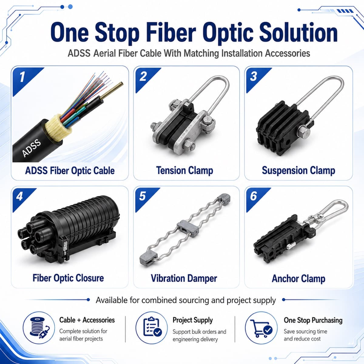
Direct answer: assign hardware from the pole role
For a CIS ADSS route, do not multiply one generic clamp set by the number of poles. Mark each structure as tangent support, small-angle support, angle or anchor point, terminal, crossing, height-change point, downlead or splice location. Then match the hardware to the approved load case and the finished cable diameter, mechanical data and jacket—not to a span label alone.
Freeze the cable before freezing clamp ranges
A preformed set, suspension body or dead-end grip is selected around a defined finished cable. Confirm outside diameter and tolerance, jacket type, cable mass, rated tensile strength, maximum allowable tension, installation tension and the approved sag-tension case. If the cable design changes after the fittings are ordered, reopen the hardware check instead of assuming the original range still fits.
Create one pole-role matrix
The schedule should list pole ID, incoming and outgoing spans, line angle, elevation change, attachment height, route function, cable section, fitting type, quantity, vibration-control requirement, downlead or storage hardware and drawing reference. This exposes the structures that need engineering attention and prevents an isolated crossing or terminal from disappearing inside a total quantity.
Separate suspension and tension duties
Suspension assemblies normally support the cable through tangent or approved low-angle positions while longitudinal tension continues through the route. Dead-end assemblies transfer cable tension at terminals, anchors, defined angle structures, section boundaries and other locations required by the approved design. The designer or operator must define the transition rule; a supplier should not invent an angle threshold without the project standard.
Treat crossings and elevation changes as named positions
Road, river, railway and power-line crossings can introduce longer spans, clearance controls, access restrictions and separate installation sections. Significant elevation changes can also alter tension balance at a structure. Give these poles unique IDs and show whether the route requires anchors on one or both sides, a splice point, special attachment hardware or a separate cable section.
Do not add vibration dampers from span length alone
Aeolian vibration depends on the installed cable, tension, diameter, wind exposure, span and support arrangement. IEEE 1222 and IEC 60794-4 provide relevant ADSS performance context, but the quantity, type and placement of dampers still need the cable and hardware supplier's approved recommendation for the declared route. Record that recommendation on the pole schedule rather than leaving it as a field decision.
Include downlead, storage and splice hardware
At joint closures and terminal structures, show how the cable leaves the aerial attachment, is guided down the pole or tower, maintains bend radius, stores reserve and reaches the closure without rubbing the structure. Add downlead clamps, storage brackets, closure mounts, grounding provisions for any metallic accessory where applicable and the civil interface to the duct or building entry.
Check the pole and attachment interface
Cable fittings do not prove that a pole, cross-arm, bracket or tower attachment can carry the project load. Confirm pole condition, available attachment position, bracket geometry, fasteners, corrosion protection, clearance and the entity responsible for structural approval. Keep cable-and-fitting compatibility separate from pole-capacity approval, while recording both in the same design package.
RFQ checklist for an ADSS fitting package
Send the pole schedule and route drawing; typical and maximum spans; angles, crossings and elevation changes; line voltage and cable position where power structures are shared; temperature, wind and ice basis; cable datasheet; fitting standard; attachment details; vibration study or supplier recommendation; splice and reserve plan; quantities, spares, markings, inspection documents and packing destination.
FAQ: Can hardware be ordered before the final cable datasheet?
Budget quantities can be prepared, but final clamp and preformed-set ranges should follow the finished cable data and approved route loads. Otherwise a later change in diameter, jacket or mechanical design can create a grip or load mismatch.
FAQ: Does every tangent pole use the same suspension set?
Not automatically. Span imbalance, line angle, vertical load, attachment geometry and exposure can create different duties. Group poles only after the route engineer confirms they share the same design conditions.
FAQ: Should cable and hardware come from one supplier?
A coordinated package can simplify compatibility and responsibility, but it is not a substitute for route engineering. If separate suppliers are used, freeze the same cable datasheet, clamp range, mechanical loads, drawings and acceptance evidence across both contracts.
Build a pole-by-pole ADSS hardware schedule
Send the route drawing, pole list, spans, line angles, crossings, wind and ice basis, attachment height, splice points and proposed cable datasheet. We can organize the cable and fitting questions before quotation.
Send Pole Schedule