
ADSS · Project preparation
ADSS Stringing Plan: Route, Tension and Hardware Review
Before an ADSS crew starts, connect the approved route, cable limits, temporary equipment and permanent fittings in one section-specific plan. This review turns material availability into a workable project handover.
Start with one plan for each installation section
A usable ADSS stringing plan identifies the exact section, cable, drum, temporary setup, permanent fittings and responsible approver. Review these together before mobilizing a crew. A long-span project, a route with sharp changes of direction and a low-temperature installation can need different preparation even when the purchase order lists the same fibre count. Keep the plan tied to the current route drawing so the installer can see which conditions the approved supply package actually covers.
Freeze the route version and the work boundary
List the start and end supports, intermediate supports, angles, elevation changes, crossings, splice locations and access points for the section. Record restrictions affecting reel delivery, equipment positions or the permitted work window. Identify any pole modifications and temporary works awaiting engineering approval. When a survey changes a support position, review the affected setup before assigning a drum; a correct total route length does not establish that the planned pull remains practical.
Keep pulling tension and final span tension in separate fields
Corning's Solo ADSS procedure distinguishes the force applied during cable placement from the tension used to achieve the designed installed condition. For a UKCC project, obtain both requirements for the actual offered cable and approved route. Record the allowed installation pull with its document reference, then record the applicable sag-tension schedule and installation conditions separately. Rated tensile strength on a datasheet cannot stand in for either entry. This prevents a procurement summary from turning one impressive mechanical value into an unintended installation instruction.
Review equipment against the supplied cable limits
Ask the installation contractor to identify the proposed puller, tension-control and measuring arrangements, stringing blocks, pulling attachment and relevant temporary fittings. The review should show how their application fits the cable's supplied instructions, including the loaded bend requirement and the intended load transfer. Check whether a quoted dimension means radius, diameter or groove dimension before comparing it. A list that says only 'standard pulley' leaves an important interface unresolved. The contractor and responsible engineer should close equipment suitability and inspection items before the start date.
Show how corners and changes in level are handled
Mark the supports where the route changes direction or elevation and connect each to the proposed section arrangement. Ask whether the approved setup covers those positions, whether additional access or temporary equipment is required and whether the support assessment includes the installation loading. Assign an owner to any unresolved position. Keeping these questions visible helps procurement deliver the required items before a crew reaches a difficult point; the article does not supply substitute load calculations or a universal angle rule.
Match permanent hardware to the released cable
Reconcile each fitting reference with the actual cable diameter, construction, sheath and approved application. Show endpoint and intermediate roles, brackets, vibration-control items where specified, downlead protection and storage arrangements. Record the revision used to select the hardware. If the cable or a fitting changes, identify which pairings need another review. Temporary pulling attachments and permanent dead-ends have different duties, so both belong in the plan with their own references.
Connect the work plan to a continuous drum allocation
Assign a particular drum to each planned continuous section and reconcile its length with the approved end, splice and access allowances. Keep handling access and reel equipment capacity alongside the drum dimensions and mass. A late decision to split a section can affect splice materials, records and subsequent testing as well as metres. Use the existing splice-allowance and route-change guides when those assumptions change, and carry their approved outcomes into the section plan.
Close the handover with a usable record
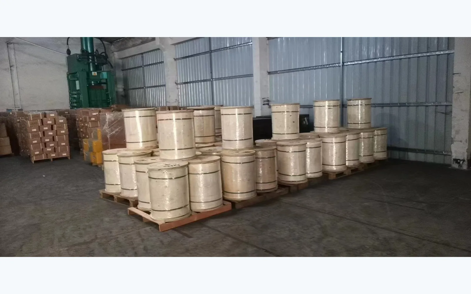
The installer should receive the section drawing, cable instructions, fitting schedule, relevant equipment information and identified open items in a controlled revision. Name the people responsible for engineering approval, installation, material release and acceptance records. After the work, retain the section and drum identity, relevant installation records and the testing required by the project. UKCC can align cable and accessory supply to that agreed scope. The cover is a factory warehouse photograph showing finished drums; it does not document an installed route or establish the contents of any individual drum.
FAQ: Can we use the tension in a different supplier's installation guide?
Use the instructions and approved design for the cable being installed. Another manufacturer's guide is useful background, but its numerical limits and setup assumptions do not define a UKCC order.
FAQ: Does a larger stringing block automatically solve a difficult corner?
No. Suitability depends on the cable requirements, block geometry, route and loading arrangement. Ask the contractor and project engineer to confirm the actual setup.
FAQ: What should change if a support or crossing moves?
Review the affected section boundary, route geometry, setup, sag-tension basis, fittings and drum assignment. Record which items remain valid and which need revised approval.
FAQ: What is the most useful information for a supplier review?
Provide a current section drawing and pole schedule with the exact cable and fitting references. Attach the project's engineering requirements and clearly mark the missing information instead of replacing it with assumed values.
ADSS prestart document and interface matrix
| Review item | Information to connect | Responsible project role |
|---|---|---|
| Route section | Support IDs, geometry, crossings, access and current drawing | Designer and construction lead |
| Cable limits | Exact cable revision, pulling limit and loaded bend requirement | Cable supplier and installation contractor |
| Installed condition | Approved sag-tension schedule and installation conditions | Responsible line engineer |
| Equipment and hardware | Temporary setup and permanent fitting references | Contractor, fitting supplier and engineer |
| Drum and evidence | Continuous length allocation, handover and acceptance records | Procurement, site team and acceptance owner |
Six steps before releasing the section plan
- Identify the current section drawing and every exceptional support position.
- Attach the supplied cable instructions and separate pulling limits from final tension requirements.
- Confirm the contractor's equipment and temporary setup review.
- Reconcile permanent fittings with the approved cable and pole roles.
- Assign a drum and record the approved continuous length and allowances.
- Close open items, record the approving roles and issue the controlled work package.
Cable and project planning references
Manufacturer background for the review
Bring the route and supply schedule into one review
Send the current pole schedule, section drawing, approved cable reference, drum allocation, sag-tension requirements and proposed fittings. Mark the outstanding equipment or engineering questions and the planned start date so we can review the material interfaces with your project team.
Send the ADSS Project Documents